Hey all! I know we have some hobbyist here who dabble in switches and soldiering(sp?) and LEDs and whatnot. I have a little question for you (don’t worry, I will research this as well when I get time).
My kids got this dune buggy thing for Christmas, which is pretty cool. However, it doesn’t even have an off switch! Which means it’s a little dangerous when they are getting in and out as they can inadvertently (or advertently) push the accelerator. I want a hard switch and indicator light to act as a safety.
I have a switch, and I have an LED with a resistor (built for (9V, but whatever, I can soldier a new one).
I can put the switch in no problem, that’s easy, just clip, soldier and go. But I want an LED indicator to show whether it’s “off” or “on” which means when the switch is flipped “on” power is coming through the switch from the battery. And the LED light should go on. When switch is off, light should be off.
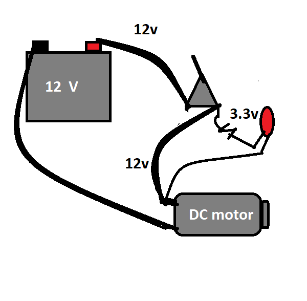
The battery is 12V lead acid and pretty hefty, with big fat wires (I don’t remember gauges off the top of my head, but I’m guessing like 10 or 8). If I put the LED straight after the switch I’m afraid it will burn it out, or I will have to put a series of resistors on it, which will cut down power to the engine. Is this one of those “parallel current” problems? I’m pretty amateur at this stuff, have only dealt with low voltage 1.5/3/9V batteries to power stuff so far. Never had to deal with a big, beefy circuit like this. Should I splice the line after the switch into two, one path for the mega current, and a resistor on the same path to the LED, then back to the ground?
Hope that question makes sense and I didn’t just embarrass myself. :)
You have the right idea. You want the Led in parallel or the LED will explode as the current supplying the motor goes through it. However, do not wire the outgoing end of the LED upstream of the motor. Instead wire it to bypass the motor. If you don’t, the electricity will see the path as an alternate way to get to the motor, and some of the motors current flow will go through it.
Here is the important part: Your connections, and the AMP rating of your switch. Those big beefy wires are beefy so they can supply high current flow. If you put a dinky little switch there with a small little dab of solder, the high current may cause heating and melting at that point. Do you have access to the motor? All electrical motors should have a plate on them indicating the various ratings Take a pic of that for me and we can be sure of the things we need in the control circuit and how many amps are going to be flowing through your connections.
If you cant provide that, then a pic of the wires with a pen for scale will have to suffice. The voltage ratings of your LED is also important, so we can make sure that in conjunction with your resistor, its not pulling to many amps. Have a voltmeter? just take a resistance reading on both leads of the LED and tell me the ohms you see in both the LED and your resistor.
This circuit design is simple and cheap, but there are other solutions if the AMP draw is too big for your switches and connections, that will require a motor control switch.
Good point about bypassing the motor completely. That’s what draws the big power, duh. So my ground would go from the switch ground to the LED, then to the battery directly?
The switch is pretty beefy, I’ll show it to you as well.
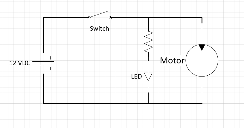
Your schematic as drawn won’t work. (I think that’s what @Mr.GRIM is saying.) You’ve basically got a short across the LED/resistor combo. You want it to look like this:
Where V_diode is the forward voltage drop of the LED (typically about 1.5V) and I_diode is the rated current of the LED, which you can find on its datasheet. Hobbyist LEDs often run between 10 and 100 mA.
So for a 1.5 V/10 mA diode, you’d have R = (12-1.5)/0.010=1050 ohms. There’s no precision necessary for LEDs and if you’re off by a factor of 2 or 3 you’ll be fine–err on the side of higher resistance rather than lower.
And yeah, @Mr.GRIM’s note about making sure your switch is rated for the motor current is apropos. High current switches are relatively cheap. (Here are a few that work for 16A loads and cost less than $10, and I’m sure you can find many similar ones at Home Depot. You can probably even easily find one with a key. You want a SPST (single pole/single throw) switch.) Don’t use something meant for breadboarding or low voltage circuits.
Also, I wouldn’t use solder for this kind of circuit. Use crimp-on quick connect terminals/spades if you can or a switch with screw terminals.
:) I do this kind of thing for a living. I’d only use solder for a circuit or component that’s tacked down to something else or in addition to crimping. Solder doesn’t provide any kind of strain relief, and it doesn’t tolerate temperature extremes very well. For the LED and resistor, I’d use butt splice crimping terminals with either electrical tape or shrink tubing to insulate exposed wires and for strain relief.
Beat you to it! What’s funny is that before I had my current job, I did almost no electronics work on the bench and couldn’t really have provided any practical advice for this kind of project at all. My previous job was all CAD/software. I’ve spent the last decade, though, doing everything: soldering, wiring, assembling, splicing, repairing, etc and also working closely with the techs that do that stuff full-time. My system design skills are immeasurably better for it. 90% of good engineering, particularly at my facility–which is doing primary science research and has lots of one-off projects with time-to-operation as a bigger constraint than price or field robustness–is design for installation/maintenance/repair.
That butt splice is similar to a bunch of F/F connectors I used to have for small wire work (good for breadboard building as connector pieces). That’s gonna save a lot of resistor soldering time in the future.
Some of those have solder and heat shrink built into them. You just put the wires in, lightly crimp, then heat it with a heat gun, which melts the solder and shrinks the tube. Pretty cool!
It fits the bill with no on/off, but says it is 24V, requiring 2 x 12V lead acid batteries. Anyways, the motor plate is ideal because that gives us the specs of what you have in front of you with no doubts.
An LED has a positive and a negative. In MattW nice drawing the positive is the side closest to the resistor. I haven’t seen one in years but there was a flat side on the plastic showing the positive lead.
So, official information seems hard to come by from the company, but according to hobbyists the buggy uses a pair of 12v-RS-550 motors (1 on each rear wheel).
Looking at how they built it makes me think you will have a lot of trouble getting at a name plate, if there even is one. So lets go with these specs. You have 11 amps per motor, so you will need to make sure your switch is rated for at least 22 amps, but since that is an uncommon number, your looking for a 25 or 30 amp rated switch.
Good advice on connections above, 25 amps is no small amount of current flow, so make sure your connections are solid to handle the constant vibration, and beefy to handle the amps. Good luck!
And on a semi-related note, I was in Hanoi a couple of years ago. We stayed in the Old Quarter district near Hoàn Kiếm Lake. The streets surrounding the lake close to vehicle traffic at night and on one of the nights we were there, vendors set up 100’s of power wheels for tourists and locals to rent so their kids could drive around on the street
There must be some Rule 34 thing for DIY projects. If you can imagine it, someone has done a tutorial on it. :) Thanks! Man, I was gonna go all Mad Max post-apocalypse on it, but buying a few parts meant to do this kind of thing seems better. Before civilization collapses, anyway.